Building a Universal Remote with an Arduino
It is really easy to build a universal remote using an Arduino. With just an infrared LED, it can impersonate remotes for your TV, fans, lights, etc. and can let you easily incorporate these into your electronics projects. You won’t even have to solder anything or void any warranties.
For a project I’m working on, I need to emulate the remote for a Lutron Maestro light dimmer. It uses a modulated IR signal, which is a common way for remotes to communicate and is easy to generate with an Arduino. The basic scheme is simple: each command is sent as a series of pulses representing bits, which can be either 1 or 0. To send a 1, you rapidly blink the LED on and off at 38 kHz, and for 0 you leave the LED off. (The 38 kHz modulation makes the signal more resistant to interference from other light sources).
Decoding the Signal
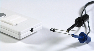
To decode what the remote was sending, I used an oscilloscope and a small photodiode. The photodiode generates a small amount of voltage when light hits it, and responds to changes in light level quickly enough that the oscilloscope can draw a really nice plot of the signal. I have a Parallax USB oscilloscope, which is perfect for showing the command pulses and is just fast enough to find the modulation frequency. As an aside, I’m really happy with the Parallax oscilloscope for projects like this. It is simple to use and I love being able to save images to share with people.
Here’s what two of the commands from the dimmer remote look like. The top signal is the “fade lights up” command, and the bottom one is “fade lights down”:
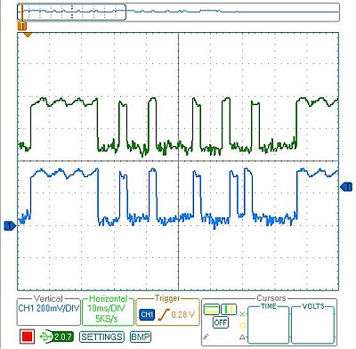
I captured several different commands, then measured the length of all the pulses. Looking at all the commands, a couple patterns are obvious:
- The entire command takes 82.8 ms (after which it immediately repeats, presumably because I held the button on the remote down a little too long).
- The lengths of the on/off pulses are all multiples of 2.3 milliseconds (which means that the entire 82.8 ms command represents 36 bits of data).
- The last four bits are always 0, so really each command is four bytes long, followed by four 0 bits
The particular remote I’m emulating has five commands, and once they are decoded they look like this:
fade up        = [255, 136, 130, 34]
fade down      = [255, 136, 130, 20]
full on        = [255, 136, 132, 184]
full off       = [255, 136, 189, 18]
memory recall  = [255, 136, 132, 183]
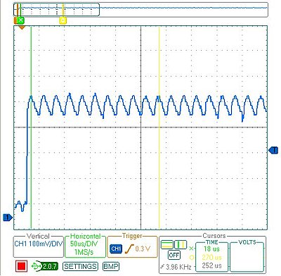
The one other missing piece of information is the modulation frequency which can be measured by zooming in on any of the pulses. This remote uses a frequency of 39.68 kHz. (In the plot below, it says the frequency is 3.96 kHz because I included 10 pulses in the measurement to increase accuracy)
Programming the Arduino
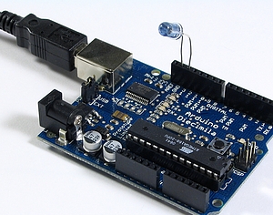
Using an Arduino makes the circuit really simple. I put an IR LED between pin 13 and ground. Since pin 13 has an internal resistor, that’s all that’s required. The code is also pretty straightforward:
/* Control a Lutron Maestro light dimmer */
#define BIT_IS_SET(i, bits)  (1 << i & bits)

// LED connected to digital pin 13
const int LED_PIN = 13;
// Width of a pulse, in microseconds
const int PULSE_WIDTH = 2300;
// # of bytes per command
const int COMMAND_LENGTH = 4;

const int UP[]     = {255, 136, 130, 34};
const int DOWN[]   = {255, 136, 130, 20};
const int ON[]     = {255, 136, 132, 184};
const int OFF[]    = {255, 136, 189, 18};
const int RECALL[] = {255, 136, 132, 183};

void setup()
{
  pinMode(LED_PIN, OUTPUT);
}

/* Modulate pin at 39 kHz for give number of microseconds */
void on(int pin, int time) {
  static const int period = 25;
  // found wait_time by measuring with oscilloscope
  static const int wait_time = 9;

  for (time = time/period; time > 0; time--) {
    digitalWrite(pin, HIGH);
    delayMicroseconds(wait_time);
    digitalWrite(pin, LOW);
    delayMicroseconds(wait_time);
  }
}

/* Leave pin off for time (given in microseconds) */
void off(int pin, int time) {
  digitalWrite(pin, LOW);
  delayMicroseconds(time);
}

/* Send a byte over the IR LED */
void send_byte(int bits) {
  for (int i = 7; i >= 0; i--)
  {
    if (BIT_IS_SET(i, bits)) {
      on(LED_PIN, PULSE_WIDTH);
    } else {
      off(LED_PIN, PULSE_WIDTH);
    }
  }
}

/* Send a full command */
void command(const int bytes[]) {
  for (int i = 0; i < COMMAND_LENGTH; i++) {
    send_byte(bytes[i]);
  }
  off(LED_PIN, 4 * PULSE_WIDTH);
}

void loop()
{
  command(UP);
  delay(1000);
  command(DOWN);
  delay(1000);
}
Checking the Arduino with the Oscilloscope
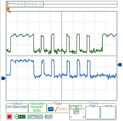
After programming the Arduino, I used the oscilloscope to check the output of the Arduino vs. the original remote. On my first attempt, the wait_time in on() was too long, so the command was stretched out. I hadn’t accounted for the fact that the digitalWrite() calls would consume some time, so I just decreased wait_time until the length of the overall command was correct. As you can see, the final synthesized command overlaps exactly with the authentic one. The green signal on top is from the remote, and the blue signal on the bottom is the arduino:
Final Test
Once everything was ready to go, it was time for the last test: I tried using the Arduino in place of the remote and it worked! It was able to control the light dimmer flawlessly. This lets me finish my project, plus now that I have all the code written it should be easy to adapt to other remote control devices.